
Are you planning to upgrade your home’s electrical system, add some brilliant new smart lighting, or finally install that electric vehicle (EV) charger in the garage? If so, you are stepping into an exciting world of home improvement. As we move deeper into 2026, the trend of upgrading our living spaces with smart technology is absolutely booming. From Internet of Things (IoT) connected lighting to automated climate control, our homes are getting smarter every single day. But before you grab a wire stripper or start dreaming of a high-tech paradise, you need a solid game plan. That is exactly where house wiring diagrams come into play.
Think of house wiring diagrams as the ultimate roadmap for your home’s electrical nervous system. They take the mystery out of the walls and put a clear, safe plan right in your hands. Whether you are a curious DIY enthusiast looking to understand your breaker box or a homeowner preparing to hire a professional, understanding these blueprints is completely essential. They keep you safe, save you money, and ensure your upgrades meet the strict 2026 building codes.
| Type | Description | Best For | Example Use Case |
|---|---|---|---|
| Schematic | Shows electrical flow with symbols | Troubleshooting circuits | Tracing power from panel to outlet |
| Pictorial | Realistic images of components | Visual beginners guide | Illustrating switch-to-light runs |
| Wiring/Layout | Physical room layouts and paths | Installation planning | Room-by-room outlet placements |
| Block | High-level components overview | System planning | Main panel to sub-circuits |
Types of House Wiring Diagrams
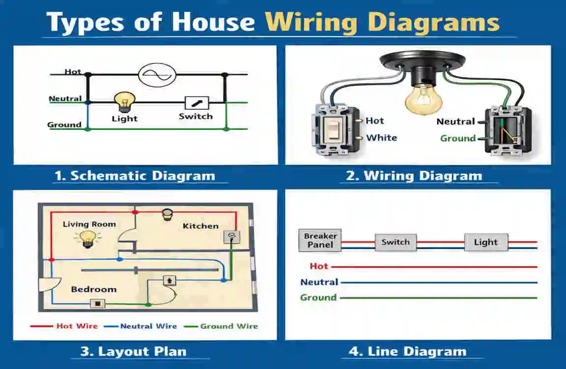
When you first hear the phrase “house wiring diagrams,” you might picture a chaotic jumble of lines and numbers that only an engineer could understand. But do not worry! Electrical diagrams actually come in a few different flavors, and each one serves a very specific, easy-to-understand purpose. By breaking them down, you can choose the exact map type you need for your specific project.
The Schematic Diagram
A schematic diagram focuses purely on how the electricity flows from one point to another. It does not care about what your living room actually looks like or where the sofa sits. Instead, it uses simple lines and standardized symbols to show how a circuit works. You use a schematic when you want to understand a circuit’s logic, like figuring out how a single switch controls a ceiling fan. It strips away the physical reality and shows you the pure electrical path.
The Pictorial Diagram
If you are a visual learner, the pictorial diagram will be your best friend. Instead of using abstract symbols, pictorial house wiring diagrams use realistic drawings of the actual components. You will see a drawing that actually looks like a light switch connected by colored lines to a drawing of a light bulb. These are incredibly popular for DIY beginners because they show you exactly what the physical wires will look like when you open up an electrical box in your wall.
The Layout Diagram
Finally, we have the layout diagram. This is the big-picture view. It takes a standard architectural floor plan of your house and overlays the electrical components onto it. You will look down at your house from a bird’s-eye view and see exactly where every outlet, switch, and light fixture is located in the physical space. Layout diagrams are absolutely vital when you are doing major room renovations or building a house from scratch, as they tell the electrician exactly where to drill holes and run cables.
Essential Symbols Guide
If house wiring diagrams are maps, then electrical symbols are the alphabet you need to read them. At first glance, these little squiggles and circles might look like an alien language. However, once you learn a few of the most common symbols, you will find that reading a diagram becomes second nature. Let us break down the basics so you can start decoding your home’s electrical plan right away.
To keep things simple, electricians use a universal set of symbols to represent physical objects. A straight line always represents a wire. A circle usually indicates a light fixture. By memorizing these core shapes, you can easily figure out what is happening on the page.
Here is a handy table showing some of the most critical symbols you will find on standard house wiring diagrams:
Symbol Description Use Case
— A straight line represents a live, neutral, or ground wire carrying the current.
The Circle / Light bulb indicates a ceiling or wall-mounted lighting fixture.
⊥ Switch symbol: Shows a standard single-pole light switch used to break the circuit.
= Double parallel lines represent a standard wall outlet (receptacle) where you plug in devices.
G Ground symbol (tree-like): Shows where the circuit safely grounds to the earth to prevent shocks.
Take a few moments to study these shapes. Once you know that a circle is a light and a straight line is a wire, you can easily trace the path of power across the page!
Safety First: Key Rules
Before we go any further, we need to have a serious conversation about safety. Electricity is incredibly powerful, and it demands your absolute respect. Even if you are drawing house wiring diagrams and planning to hire a professional for the physical labor, you need to understand the fundamental safety rules that govern modern electrical work. In 2026, the National Electrical Code (NEC) has strict guidelines designed to keep your home from catching fire and to protect you from nasty shocks.
First and foremost, the golden rule of any electrical work is to always turn off the main breaker before opening a panel or touching a wire. You should never, under any circumstances, assume a wire is “dead.” Always use a non-contact voltage tester to double-check that the power is truly off before you begin your work.
Furthermore, you must always use insulated tools. If you drop a regular metal screwdriver inside a live electrical panel, it can cause a catastrophic spark. Insulated tools feature rubber coatings that protect your hands from stray currents.
Another massive rule for 2026 is proper grounding. Every single circuit in your home must have a dedicated ground wire. This wire acts as a safe emergency escape route for electricity if something goes wrong with an appliance. Finally, you must never overload a circuit. If your diagram shows ten heavy-duty appliances on a single 15-amp breaker, you are designing a fire hazard. Always spread your heavy electrical loads across multiple dedicated circuits.
Tools for DIY Wiring
If you are planning to take a hands-on approach to your home’s electrical system, you need the right gear in your toolbox. You cannot successfully execute what you draw on your house wiring diagrams using a butter knife and some old tape. Modern DIY electrical work requires a few specific, highly reliable tools.
For the physical work, your most important tool is a high-quality digital multimeter. This device lets you measure voltage, current, and resistance, ensuring that your circuits are functioning exactly as your diagram intended. Next, you will need a sturdy pair of wire strippers. These allow you to cleanly remove the plastic insulation from your copper wires without accidentally cutting the metal inside. Add in some lineman pliers, electrical tape, and a set of insulated screwdrivers, and your physical toolkit is ready to go.
But what about creating the diagrams themselves? You do not need to be an artist to make a great plan. We highly recommend using digital software to map out your home. Programs like EdrawMax or other free online diagramming tools offer drag-and-drop templates. You select a “switch” icon, drag it onto your screen, and draw a digital wire to your “lightbulb” icon. It makes creating clean, professional-looking house wiring diagrams incredibly easy, even if you have zero drawing skills.
Reading House Wiring Diagrams
You have learned the symbols and gathered your tools. Now, how do you actually read these diagrams? The secret is to stop looking at the entire page all at once. If you look at the whole house, you will get overwhelmed. Instead, you need to trace the flow of electricity step-by-step, just like you would trace water flowing through a plumbing pipe.
Start at the very beginning: the main service panel (your breaker box). On the diagram, find the specific circuit breaker you want to study. Let us say it is the breaker labeled “Living Room Lights.” From that breaker, follow the straight line (the wire) with your finger.
You will trace that line across the page until it hits a switch symbol. This means the power flows directly from the breaker to the light switch on your wall. Next, trace the line coming out of the switch. You will see it travel to a circular symbol that represents your ceiling light. Finally, trace the neutral wire (the return path) from the light fixture back to the main panel.
That is it! You have just successfully read a complete circuit. Electricity always needs a closed loop to work. It travels out from the breaker, does a job (like lighting a bulb), and travels back home. When you view house wiring diagrams as a series of simple, continuous loops, they suddenly become incredibly easy to decode.
Single-Phase House Wiring Basics
If you live in a standard residential home, you are almost certainly dealing with a single-phase electrical system. But what exactly does that mean? Let us break down the basics of single-phase power so you can understand the heartbeat of your home.
In a single-phase system, the power company sends electricity to your house using three main wires that connect to your outdoor electrical meter. Two of these wires are “hot” (carrying live voltage), and one is “neutral.” When these wires enter your home, they connect directly to your main breaker panel. This setup provides you with the standard 120/240V power that runs everything in your life.
Inside your main panel, you will find two heavy metal strips called bus bars. Each hot wire connects to one of these bus bars. If you need 120 volts of power (for standard things like a television or a table lamp), a circuit breaker connects to just one of those bus bars. If you need a massive 240 volts of power (for heavy-duty items like an electric oven, a clothes dryer, or a 2026 rapid EV charger), a double-pole breaker connects to both bus bars simultaneously.
Your house wiring diagrams will clearly show this flow. You will see the power enter the Main Circuit Breaker (MCB), which acts as the master switch for the entire house. From the MCB, the power flows down the bus bars and splits off into individual, smaller breakers. Understanding this meter-to-panel flow is the absolute foundation of residential electrical knowledge.
Room-by-Room Diagrams
Every room in your house has a different job, so each needs a different electrical layout. A bedroom does not need the same heavy-duty power as a kitchen. Let us explore what typical room-by-room house wiring diagrams look like in a modern home.
The Kitchen Layout
The kitchen is the most power-hungry room in the house. Your layout diagram here will look very busy. The 2026 electrical codes require multiple 20-amp dedicated circuits for the kitchen. You will see separate, thick wires running specifically to the refrigerator, the microwave, and the dishwasher. Furthermore, every single outlet located near your kitchen counter must be a GFCI (Ground Fault Circuit Interrupter) outlet to protect you from water-related shocks.
The Bedroom and Living Space Layout
Bedrooms and living rooms are much simpler. Your diagrams will show standard 15-amp circuits powering the wall outlets and ceiling lights. However, modern living spaces often feature smart dimmers and integrated ceiling fans. Your diagram will show a loop going from the door switch to the ceiling, with power branching off to the various wall receptacles where you plug in your phone chargers and televisions.
The Garage and Utility Layout
Garages have evolved rapidly. A standard 2026 garage diagram will show heavy 240V circuits running to the wall to prepare for EV chargers. You will also see dedicated lines for heavy power tools and deep freezers.
By isolating your house wiring diagrams room by room, you ensure each area gets the exact amount of safe power it needs to function perfectly.
Smart Home Integration
Welcome to the future! Building or upgrading a home in 2026 means you are likely thinking about smart home integration. We no longer just run power to a lightbulb; we run data. When you look at modern house wiring diagrams, you will see a whole new layer of connectivity that did not exist ten years ago.
Today’s smart homes require robust communication networks. Alongside your standard electrical wires, your layout diagrams will now include low-voltage wiring. You will see pathways for CAT6 ethernet cables running to every room, ensuring lightning-fast internet for your smart TVs and home office setups. You might also map out the hidden HDMI cables running through the walls from your media console to your mounted flat-screen.
But the biggest change is in the lighting and climate control. Smart switches and automated systems often rely on NodeMCU relays and Wi-Fi-enabled controllers. A modern schematic will show how a smart relay sits between your breaker panel and your ceiling fan. This relay acts as a tiny, internet-connected brain that lets you turn the fan on from your smartphone, even if you are miles away from home. When drawing house wiring diagrams today, you must always leave extra room in your electrical boxes to accommodate these slightly bulkier smart home switches.
Common Mistakes to Avoid
Even with the best house wiring diagrams in hand, it is incredibly easy for DIYers to make dangerous mistakes. Electricity is unforgiving, so knowing what to avoid is just as important as knowing what to do.
One of the most frequent errors is overloading a circuit. Just because a room has six outlets does not mean you can plug six heavy space heaters into them. If your diagram attempts to put the kitchen microwave, the toaster, and the living room TV on the same 15-amp breaker, you will constantly trip that breaker. Always calculate the total wattage of the appliances you plan to use and ensure the circuit can safely handle the load.
Another massive mistake in 2026 is ignoring AFCI (Arc-Fault Circuit Interrupter) protection. While GFCI protects you from water, AFCI protects your home from fire caused by sparking (arcing) wires behind the drywall. Modern codes require AFCI breakers for almost all living areas, including bedrooms and hallways. If your house wiring diagrams do not specify AFCI breakers for these zones, your plan is dangerously outdated and will fail a modern electrical inspection.
Lastly, do not overcrowd your electrical boxes. Cramming too many thick wires into a tiny plastic wall box can damage the insulation and cause a short circuit. Always plan for appropriately sized junction boxes!
Step-by-Step: Create Your Diagram
Are you ready to create your own electrical map? Drawing house wiring diagrams from scratch is highly rewarding when you take it step by step. Do not rush; grab a pencil and some grid paper, or open up your favorite digital drawing software, and follow these three simple steps.
Assess Your Electrical Load. Before you draw a single wire, you need to know how much power you need. Walk through the space and list every appliance, light, and device you plan to plug in. Using the NEC load calculation guidelines, add up the total wattage. This math tells you exactly how many circuit breakers you need and whether to use standard 15-amp or thicker 20-amp wires.
Sketch the Physical Layout. Next, draw a basic floor plan of your room—Mark exactly where the windows and doors are. Once the room is drawn, decide where you physically want your outlets and switches to live. A good rule of thumb is to place an outlet every 12 feet along a wall so you never have to use a dangerous extension cord. Mark these locations clearly on your paper.
Add the Symbols and Connect the Lines. Now it is time to bring the diagram to life. Replace your rough marks with the official electrical symbols we learned earlier. Draw a line from the breaker panel to represent your power source. Route that line to your first switch or outlet, and then daisy-chain the power to the next device on that circuit. Use a red marker for your hot wires, a black marker for your neutral wires, and a green marker for your grounds to keep your house wiring diagrams incredibly organized.
Advanced: 3-Way Switches & Panels
Once you master a simple room, you might run into scenarios that require a bit more brainpower. The two most common advanced elements you will find on house wiring diagrams are 3-way switches and subpanels.
A 3-way switch is what allows you to control a single light fixture from two different locations. You use these at the top and bottom of a staircase, or at both ends of a long hallway. The diagram for a 3-way switch looks a bit confusing because it requires an extra wire called a “traveler.” The power comes into the first switch, travels down the traveler wire to the second switch, and then finally goes up to the lightbulb. Drawing this out beforehand is essential because if you cross the traveler wires during physical installation, the switches will not work properly!
Subpanels are another advanced trick. If you are building a large addition or a detached workshop, running twenty different wires all the way back to your main house panel is expensive and messy. Instead, your house wiring diagrams will show a single, thick cable running from the main house panel to a smaller “subpanel” in the new workshop. This subpanel then breaks the power down into smaller circuits specifically for that new space.
Cost Breakdown
How much does it actually cost to wire a house? While house wiring diagrams are virtually free to draw, turning those lines into physical copper and plastic requires a budget. Let us look at a standard cost breakdown for a typical 1500-square-foot home doing a full DIY electrical update.
For a house this size, you can expect to spend between $500 and $2,000 on raw materials. The biggest expense is the wire itself. Massive spools of Romex cable (the standard plastic-sheathed copper wire inside your walls) can eat up a huge chunk of your budget, especially as copper prices fluctuate.
Next, you will need to buy the actual electrical panel and the required circuit breakers. Remember, modern AFCI and GFCI breakers are significantly more expensive than old-school standard breakers. Finally, you will budget for the “trim” phase. This includes your plastic junction boxes, wall outlets, light switches, and decorative faceplates. If you choose to upgrade to smart-home dimmers and Wi-Fi switches, you’ll push your budget closer to $2,000.
Free Downloadable Diagrams

You do not have to reinvent the wheel! If creating house wiring diagrams from scratch feels too overwhelming, there are countless resources available to give you a head start.
While every home is unique, the basic flow of a bedroom, bathroom, or kitchen circuit remains largely the same across standard single-family homes. Many educational platforms, DIY community forums, and manufacturer websites offer completely free, downloadable PDF templates. You can easily find pre-made schematics for 3-way switches, standard 20-amp kitchen layouts, and main breaker panel configurations.
We recommend requesting these templates from reliable DIY resource libraries or signing up for home-improvement newsletters that offer free layout guides. You can take these pre-drawn PDFs, print them, and use them as a sturdy foundation to customize the layout for your home.
FAQs
To wrap things up, let us answer some of the most frequently asked questions we hear from homeowners navigating the world of electrical planning.
Do I legally need a house wiring diagram to do work? In many jurisdictions, yes. If you are pulling an official permit to do major electrical work on your home, the local building inspector will usually require you to submit a layout diagram to prove your plan meets the 2026 safety codes before you start.
Can I draw a diagram by hand, or do I need software? You can absolutely draw it by hand! As long as you use standard symbols, a ruler, and clear labels, a hand-drawn schematic is perfectly acceptable. However, free software makes it much easier to erase mistakes and share your plan with others.
Where can I find the 2026 electrical codes for my diagram? The National Fire Protection Association (NFPA) publishes the National Electrical Code (NEC). You can view the guidelines online or check out a copy at your local public library to ensure your planned circuits are fully compliant.
What is the difference between a neutral and a ground wire on a diagram? The neutral wire carries the electricity back to the panel to complete the normal circuit loop. The ground wire does nothing during normal operation; it is an emergency safety path that safely grounds rogue electricity if a wire breaks or a machine shorts out.